Privacy choices

Choose how this site measures visits.

Essential browser storage remembers your choice. Optional analytics and advertising technologies load only with your permission. Read our privacy notice.

Skip to content

Technical guides

Designing Parts for CNC Machining

Review tool access, internal corners, feature depth, wall stability, and datum strategy before releasing the drawing.

Engineering overview

Make the design easier to machine without losing its function.

Design for manufacturability is not a request to simplify every part. It is a structured review of which geometry is functionally fixed and where radii, depth, access, wall thickness, or datum choices can be adjusted. The final manufacturing approach still depends on the complete model, drawing, material, and quantity.

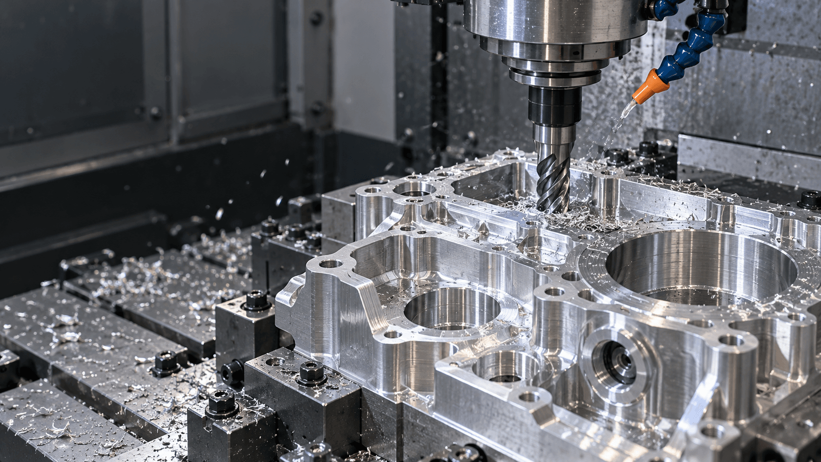
Milling tool cutting a metal workpieceRepresentative visual

Process comparison

Features to review before drawing release

Use the model to find access and stability risks, then use the drawing to distinguish fixed requirements from permitted changes.

Design areaMachining considerationUseful design input
Internal cornersRotating cutters leave a radius; deeper pockets usually need longer tools.Allow a practical internal radius or identify the mating geometry that controls it.
Deep pocketsTool reach, chip evacuation, and wall deflection become more important as depth increases.Show the required floor, wall, corner, and finish conditions.
Thin wallsClamping and cutting forces can move a flexible section.Identify the functional thickness and where added support or stock is permitted.
Holes and threadsDepth, diameter, thread engagement, and tool approach affect process choice.Specify standard, pitch, class, depth, and whether a through feature is acceptable.
UndercutsRestricted access may require special tooling, orientation, or an alternate design.Explain the interface so reliefs, split features, or alternate access can be considered.

Begin with the functional interfaces

Mark what cannot change before reviewing manufacturability. A supplier can only suggest useful alternatives when the fixed fits, sealing areas, load paths, and assembly relationships are clear.

  • Identify mating and locating features.
  • Mark critical-to-function dimensions and datums.
  • Separate appearance requirements from mechanical interfaces.
  • List features that may be adjusted after review.
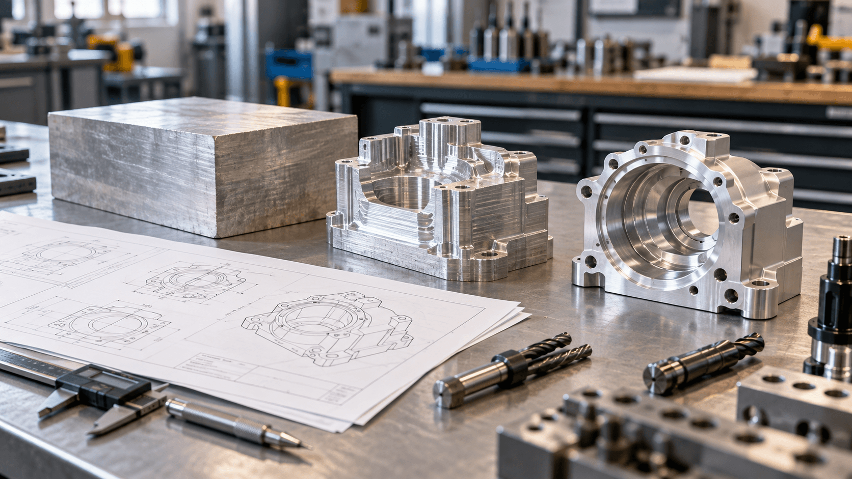
Mark critical dimensions

Create practical tool access

Every machined surface needs a feasible approach for the cutter and workholding. Review deep pockets, narrow slots, small corner radii, angled features, and hidden intersections together.

  • Allow internal corner radii where the design permits.
  • Review depth relative to opening width and tool reach.
  • Avoid inaccessible sharp internal geometry unless function requires another process.
  • Show cross-holes, internal threads, and undercuts clearly in section views.
Compare milling and turning geometry
Milling tool cutting a metal workpiece

Technical guides / Manufacturing context

Clear drawings keep technical decisions connected.

Representative media supports the engineering discussion and does not document a specific customer order.

Representative visual
03 / Project considerations

Protect stability during machining

Thin walls, slender shafts, broad flat sections, and interrupted features can respond to clamping, cutting, and material stress. Geometry and process sequence need to be reviewed together.

  • Highlight thin walls and long unsupported features.
  • Use consistent wall thickness where function permits.
  • Identify surfaces that must remain flat or aligned after material removal.
  • Discuss stock condition, finish state, and critical inspection timing.
Review tolerance inputs
04 / Project considerations

Release one controlled definition

DFM decisions only become useful when they are incorporated into the model and drawing. Informal suggestions should not compete with a different released revision.

  • Update model and drawing together.
  • Record accepted changes and unresolved questions.
  • Keep part number, units, and revision consistent across files.
  • Recheck material, finish, quantity, and inspection notes before RFQ.
Use the RFQ checklist

Before you request a quote

Designing Parts for CNC Machining FAQ

Use these answers to prepare the requirements for your part. Project details are confirmed during drawing review.

Does DFM mean changing the function of my part?

No. DFM starts by identifying the requirements that protect function. Possible geometry or process changes should be reviewed against those requirements and only adopted after the design owner approves them.

Why do internal corners need a radius?

A milling cutter rotates, so it creates a radius in an internal corner. Very small radii can require smaller, longer, or less rigid tooling. If a mating part needs clearance, corner relief may be another design option.

Are thin walls impossible to machine?

Not necessarily. Feasibility depends on material, size, support, surrounding geometry, required variation, and process sequence. Mark the required wall and functional surfaces so they can be reviewed in context.

When should I request a DFM review?

Before the drawing is fully released or whenever a critical manufacturing question remains. Provide the model, preliminary drawing, material, quantity, and the requirements that cannot change.

Ready for engineering review

Have a part to make?

Send your drawings and let our engineering team review your project.

We will provide your quotation within 24 hours after we receive complete drawings and project requirements.

Make the requirements clear

Include quantity, material, finish, critical dimensions, and any inspection requirements.

STEP / STP / IGES / IGS / STL / DWG / DXF / PDF / ZIP / XLSX / XLS / CSV