Privacy choices

Choose how this site measures visits.

Essential browser storage remembers your choice. Optional analytics and advertising technologies load only with your permission. Read our privacy notice.

Skip to content

Technical guides

How to Identify Critical Dimensions on a CNC Drawing

Connect functional features to datums, tolerances, and inspection priorities so drawing requirements are clear before quotation.

Engineering overview

Dimension the function, not only the geometry.

A critical dimension is one whose variation can affect a defined function such as fit, location, motion, sealing, or assembly. Start with the mating interface, identify the feature and datum relationship that control it, then state how acceptance should be checked. This guide helps distinguish those requirements from general dimensions; the drawing owner remains responsible for selecting engineering limits and applicable standards.

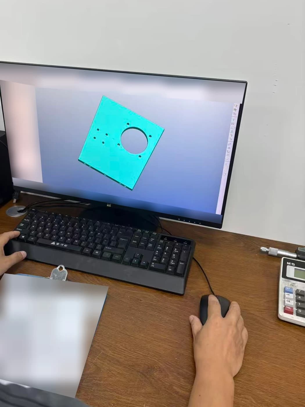
CAD model displayed at a workstationRepresentative visual

Process comparison

Translate function into drawing controls

Begin with the assembly condition, then define the feature, datum, and inspection requirement that make the condition reviewable.

Functional needDrawing informationReview focus
Part locationDatum faces, locating holes, or a datum axis.Whether the datum structure reflects how the part is assembled and measured.
Fit or motionLimit dimensions or a fit designation on the mating diameter or width.Mating-part information, operating clearance, and surface condition.
SealingSealing face, flatness or form control, and applicable surface requirement.Where the seal contacts and whether finishing changes the surface.
Feature locationPosition or another suitable geometric control referenced to defined datums.The relationship between holes, bores, faces, and the assembly interface.
Inspection priorityThe feature, datum, acceptance state, and any requested record.Whether inspection matches the functional requirement and occurs before or after finishing.
AppearanceIdentified cosmetic surfaces, finish specification, and allowed visual variation.A separate acceptance standard from functional dimensions.

Start with the interface

Trace how the part locates, moves, seals, or fastens to adjacent components, then call out the dimensions that control those functions.

  • Identify mating holes, seats, bearing surfaces, and locating faces.
  • Describe fits, threads, and interface details.
  • Share mating-part information when it clarifies the requirement.
  • Separate assembly-critical features from reference dimensions.
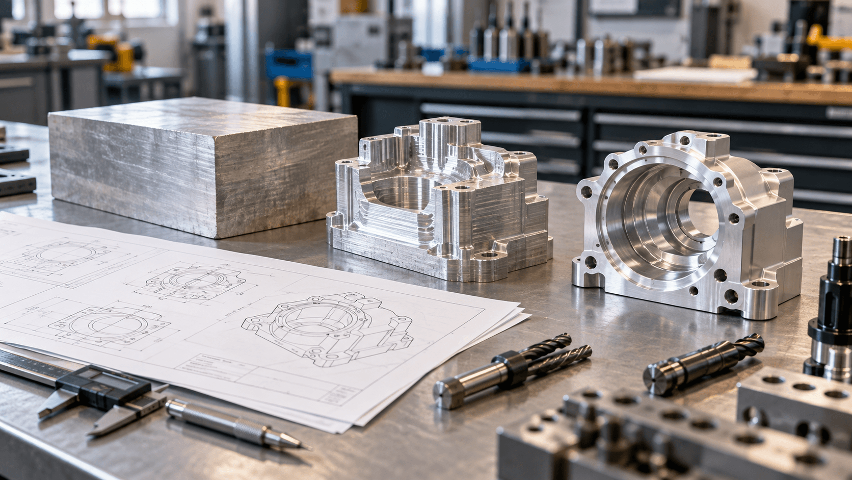
Review tolerance specification

Build a usable datum structure

Datums should represent stable features that locate the part for assembly and inspection. A datum reference that does not match the functional interface can make a drawing difficult to interpret consistently.

  • Choose a primary datum that stabilizes the part.
  • Add secondary and tertiary datums that remove the remaining movement.
  • Reference geometric controls to the functional datum system.
  • Avoid selecting small or inaccessible features unless function requires them.
See how geometry affects machining
CAD model displayed at a workstation

Technical guides / Manufacturing context

Clear drawings keep technical decisions connected.

Representative media supports the engineering discussion and does not document a specific customer order.

Representative visual
03 / Project considerations

Make inspection priorities reviewable

For each critical feature, connect the drawing callout to its functional reason and acceptance method. A short controlled list can help a quotation distinguish what must be verified from what is informational; it does not replace the drawing or applicable design standard.

  • Identify the part feature and the function it protects.
  • Reference the datum, fit, or geometric control used to evaluate it.
  • State the accepted condition, including before- or after-finish state where relevant.
  • List requested inspection records or approval steps and tie them to the drawing revision.
See the quality approach
04 / Project considerations

Keep model and revision aligned

The CAD model and drawing should describe the same design intent. A visible revision identifier helps prevent superseded requirements from being used for a quote or repeat order.

  • Include units, part number, and revision identifiers.
  • Highlight changes that affect fit or function.
  • Update the model and drawing together.
  • Remove outdated files from the RFQ package.
Use the complete RFQ checklist

Before you request a quote

How to Identify Critical Dimensions on a CNC Drawing FAQ

Use these answers to prepare the requirements for your part. Project details are confirmed during drawing review.

Does every drawing dimension need a tight tolerance?

No. Apply feature-level tolerances where variation affects fit, function, or acceptance. Unnecessarily tight requirements can limit manufacturing options and add inspection effort without improving the part.

What makes a dimension critical?

A dimension is critical when its variation can affect assembly, motion, sealing, load transfer, alignment, or another defined function. The drawing should make both the feature and its datum relationship clear.

Should cosmetic surfaces be marked as critical dimensions?

Treat cosmetic acceptance separately. Identify the visible surfaces, finish specification, masking boundaries, and visual acceptance requirements rather than mixing appearance notes with dimensional controls.

How should changed critical dimensions be communicated?

Revise the model and drawing together, update the revision identifier, and highlight the changed requirements in the RFQ or change note. Do not rely on an email description while leaving the controlled drawing unchanged.

Ready for engineering review

Have a part to make?

Send your drawings and let our engineering team review your project.

We will provide your quotation within 24 hours after we receive complete drawings and project requirements.

Make the requirements clear

Include quantity, material, finish, critical dimensions, and any inspection requirements.

STEP / STP / IGES / IGS / STL / DWG / DXF / PDF / ZIP / XLSX / XLS / CSV