Privacy choices

Choose how this site measures visits.

Essential browser storage remembers your choice. Optional analytics and advertising technologies load only with your permission. Read our privacy notice.

Skip to content

Services

CNC Turning Services

Custom CNC-turned shafts, pins, sleeves, and bushings for prototypes and production batches. Define the diameters, fits, threads, and surfaces that matter to your assembly.

Engineering overview

Turned components, built around the functional axis.

VELMEC provides CNC turning services for custom rotational components in metal and engineering plastics. Turning removes material as the workpiece rotates, making it a useful starting point for cylindrical profiles, stepped diameters, bores, and threads. We review functional diameters and their relationships alongside any features that need additional operations.

We will provide your quotation within 24 hours after we receive complete drawings and project requirements.

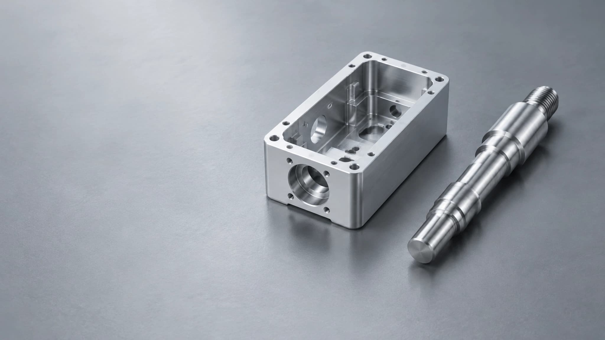
Turning tool machining a cylindrical workpieceRepresentative visual

Shafts, pins, sleeves, and bushings

Rotational parts often combine several functional surfaces. The relationship between diameters, shoulders, bores, and end faces can matter as much as each individual dimension. Identify the mating components and explain how the part locates or moves in the assembly.

  • Shafts and pins: mark bearing seats, locating diameters, shoulders, and retention features.
  • Sleeves and bushings: define the bore, outside diameter, wall thickness, and required fit.
  • Threaded parts: specify the thread standard, pitch, class, depth, and relief where required.
  • Show grooves, cross-holes, flats, and off-axis features that may require additional machining.
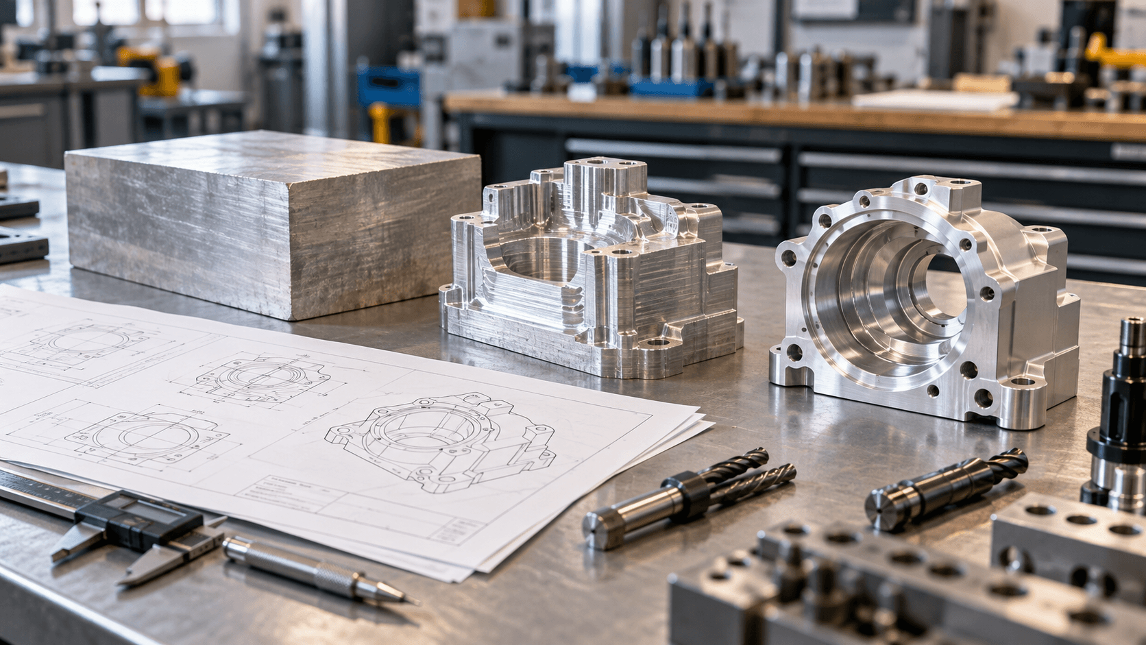
When milling and turning are used together

Material and finish for turned parts

Aluminum, stainless steel, brass, and engineering plastics are common categories considered during quotation. Specify the grade, material condition, and operating environment. Slender profiles, thin walls, and long bores need review against tool access and part support.

  • Provide overall length, largest diameter, and the dimensions of any deep bore.
  • Identify sealing surfaces, bearing fits, sliding interfaces, and cosmetic areas.
  • State the required surface roughness and any coating or treatment.
  • Clarify whether functional diameters are accepted before or after finishing.
Compare material selection requirements
Turning tool machining a cylindrical workpiece

Services / Manufacturing context

Machining decisions begin with part geometry.

Representative media supports the engineering discussion and does not document a specific customer order.

Representative visual
03 / Project considerations

Diameter tolerances, runout, and inspection

A diameter tolerance alone may not define how a turned part must function. Use the drawing to specify the datum axis and any runout, concentric relationships, or geometric controls required for the assembly. Achievable limits and inspection scope are confirmed against the complete part specification.

  • Dimension functional bores and outside diameters with explicit tolerances or fit designations.
  • Reference the appropriate datum for runout and related geometric requirements.
  • Identify thread verification and surface checks needed for acceptance.
  • Discuss dimensional reports and other inspection records before order release.
Define critical dimensions and mating interfaces
04 / Project considerations

Prepare your CNC turning RFQ

Send the current model and dimensioned drawing with a clear revision identifier. A section view can help communicate internal steps, grooves, bores, and thread details that are difficult to see from an external view.

  • Attach STEP/STP and a PDF drawing when available; state units and the governing revision.
  • List the material grade, quantity, and alternative quantities you want quoted.
  • Call out fits, threads, surface finish, secondary features, and inspection requirements.
  • Share the destination and requested date so production and shipping can be reviewed separately.
Prepare a complete machining quotation request

Tolerances and Surface Finish

Parts without a technical drawing

Standard tolerance: ±0.127 mm, following ISO 2768-m.

Metal parts with technical drawings

Precision machining capability from IT7 to IT5, with feature tolerances from ±0.05 mm down to ±0.005 mm.

Engineering plastic parts

Machining capability from IT10 to IT8, with feature tolerances from ±0.30 mm down to ±0.03 mm.

Unspecified drawing tolerances

ISO 2768-f for metal parts and ISO 2768-m for plastic parts.

Minimum machined internal radius

R0.15 mm, depending on feature accessibility and tool selection.

Machined surface roughness

  • As machined: Ra 6.3–3.2 μm
  • Smooth machining: Ra 3.2–1.6 μm
  • Fine machining: Ra 0.8–0.4 μm

Tolerance capability depends on material, nominal dimension, geometry, wall thickness, machining process and inspection method. Tolerances down to ±0.005 mm apply to selected critical features and are confirmed through drawing review before quotation.

Before you request a quote

CNC Turning Services FAQ

Use these answers to prepare the requirements for your part. Project details are confirmed during drawing review.

What is the difference between CNC turning and milling?

In turning, the workpiece rotates while a cutting tool removes material, typically producing rotational features. In milling, a rotating cutter approaches the workpiece to create faces, pockets, slots, and other geometry. A part with both cylindrical and off-axis features may need both processes.

Read the milling vs. turning guide
Can a turned part include flats or cross-holes?

Yes, those features can be included in the drawing for review. Flats, cross-holes, slots, and off-axis holes may require additional machining. The suitable operations and the relationships between those features and the turned surfaces are reviewed before quotation.

How should I specify a shaft or bushing fit?

Identify the mating component, nominal diameter, required fit or limit dimensions, and the relevant datum. Include the operating conditions where they affect material or surface selection. Do not rely on a general tolerance note to communicate a critical press fit or sliding fit.

Is there a fixed maximum diameter or turning length?

Part limits are confirmed from the drawing, material, geometry, and quantity. Share the complete envelope dimensions along with any thin walls, slender sections, or deep bores so feasibility can be reviewed before an order is placed.

Ready for engineering review

Have a part to make?

Send your drawings and let our engineering team review your project.

We will provide your quotation within 24 hours after we receive complete drawings and project requirements.

Make the requirements clear

Include quantity, material, finish, critical dimensions, and any inspection requirements.

STEP / STP / IGES / IGS / STL / DWG / DXF / PDF / ZIP / XLSX / XLS / CSV