Privacy choices

Choose how this site measures visits.

Essential browser storage remembers your choice. Optional analytics and advertising technologies load only with your permission. Read our privacy notice.

Skip to content

Technical guides

CNC Milling vs. Turning: Key Differences

Compare CNC milling and turning by geometry, features, workholding, and the drawing requirements that guide process selection.

Engineering overview

Choose the starting process from geometry, not the part name.

CNC milling and CNC turning use different cutting motions. In milling, a rotating cutter removes material from a workpiece held for the operation; in turning, the workpiece rotates against a cutting tool. Process selection depends on functional geometry, tool access, workholding, datum relationships, material, quantity, and finish—not only whether the part looks round or rectangular. A part may need both operations, subject to drawing review and confirmed manufacturing scope.

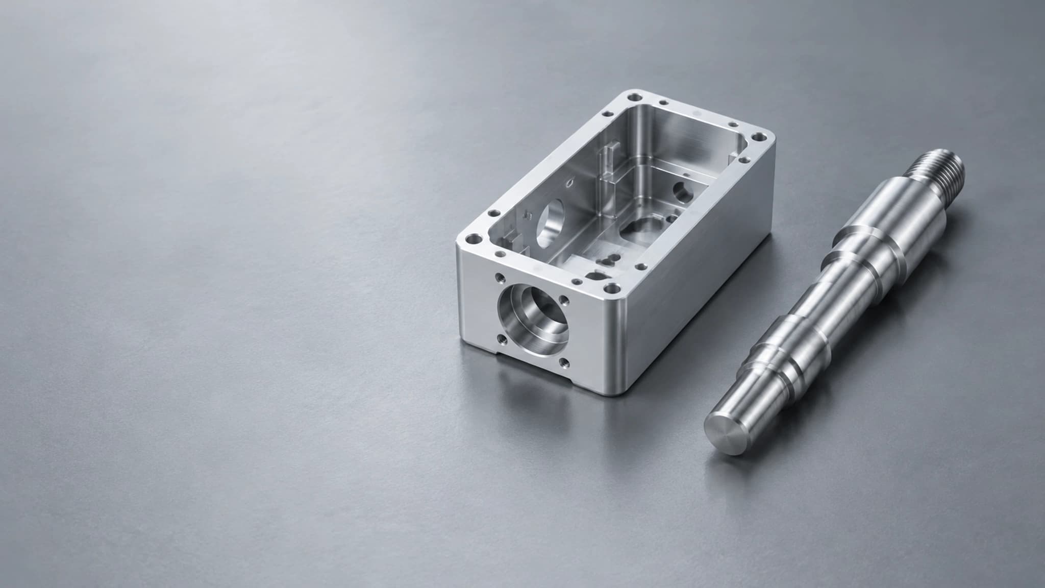
Milling tool cutting a metal workpieceRepresentative visual

Process comparison

Milling, turning, or both?

Use this comparison as a starting point. The complete drawing and model determine the final process review.

Decision factorCNC millingCNC turningCombined operations
Basic cutting motionA rotating cutter removes material from a workpiece held for the operation.The workpiece rotates against a cutting tool.The drawing may call for a sequence of milling and turning operations; equipment and scope require confirmation.
Common starting geometryPrismatic housings, brackets, plates, fixtures, and blocks.Shafts, pins, sleeves, bushings, and other rotational profiles.Cylindrical bodies with flats, slots, cross-holes, pockets, or off-axis features.
Typical feature focusFaces, pockets, slots, hole patterns, and features on multiple sides.Outside and inside diameters, shoulders, grooves, bores, and axial threads.Relationships between turned diameters and milled faces or holes.
What the drawing should clarifyDatums, hole position, flatness, tool access, and internal corner requirements.Datum axis, fits, runout, threads, slender sections, and deep bores.Which operation establishes the datum and which cross-process relationships control function.
Useful decision questionAre the main functional features faces, pockets, slots, or holes reached by a rotating cutter?Do key surfaces share an axis, such as diameters, shoulders, or bores?Do both feature groups interact, and how must their relationship be accepted?

Start with the dominant geometry

A rotational envelope usually points toward turning, while multiple planar faces, pockets, and hole patterns usually point toward milling. The starting process should establish the surfaces and datums that make later features easier to control.

  • Identify whether the main functional surfaces share a center axis.
  • Mark pockets, slots, faces, and holes that require tool access from different directions.
  • State the overall envelope, including the largest diameter or longest side.
  • Do not select a process solely from the finished part's general appearance.
Review CNC milling part types

Follow the critical relationship

Process planning should protect the relationships that control assembly or motion. A turned diameter and a milled hole may each be simple, while their positional relationship is the requirement that deserves attention.

  • Define the datum axis or locating surfaces.
  • Mark fits, runout, position, flatness, and other functional controls where needed.
  • Show which faces, bores, and holes interact with mating components.
  • Separate critical requirements from general dimensions.
Use the critical dimensions guide
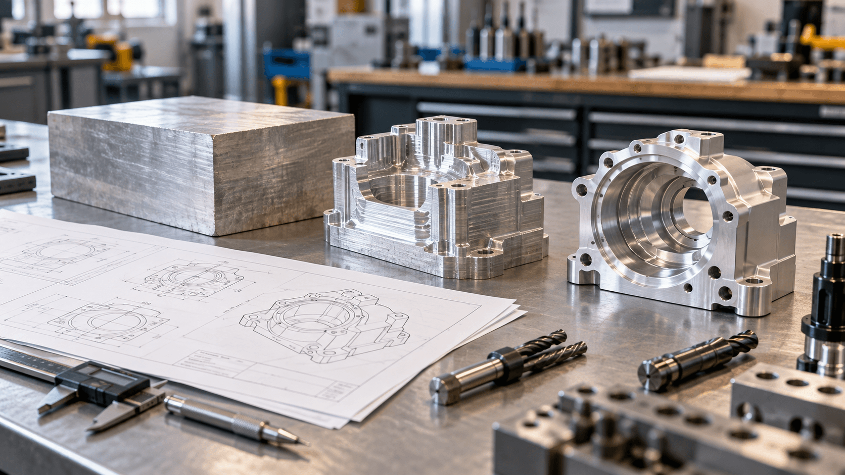
Milling tool cutting a metal workpiece

Technical guides / Manufacturing context

Clear drawings keep technical decisions connected.

Representative media supports the engineering discussion and does not document a specific customer order.

Representative visual
03 / Project considerations

When a part may need both processes

A turned profile may also contain flats, slots, cross-holes, or off-axis threads. A milled component may include rotational bores or cylindrical interfaces. Review the part as one functional definition; do not assume a specific mill-turn machine or process sequence before the drawing and manufacturing scope are confirmed.

  • Show secondary features in the model and drawing, including their datums.
  • Explain the functional relationship between cylindrical and prismatic features.
  • State finish and inspection requirements for each feature group.
  • Ask the supplier to identify the proposed operation sequence and any assumptions.
Review CNC turning part types
04 / Project considerations

Send enough information for process review

The supplier should not have to infer the manufacturing objective from a file name or a single view. A complete request makes it possible to assess geometry, material, quantity, finish, inspection, and delivery context together.

  • Attach the current 3D model and dimensioned drawing.
  • List material grade, quantity, finish, and revision.
  • Mark mating interfaces and critical characteristics.
  • State requested inspection records and the delivery destination.
Prepare a complete CNC RFQ

Before you request a quote

CNC Milling vs. Turning: Key Differences FAQ

Use these answers to prepare the requirements for your part. Project details are confirmed during drawing review.

Can a part require both CNC turning and milling?

Yes. A rotational body may also need flats, slots, cross-holes, or off-axis threads. The drawing should define the relationship between those features so the complete process can be reviewed as one manufacturing plan.

Does a round part always start with turning?

Not always. The functional surfaces, feature access, material, quantity, and datum structure matter more than the outline alone. Share the full model and drawing instead of selecting a process only from appearance.

Which process is better for a housing?

Housings commonly involve milled faces, pockets, bores, and hole patterns, but the final approach depends on the complete geometry and critical relationships. Large rotational features or secondary operations can change the plan.

What information helps with process selection?

Provide the model, drawing, material, quantity, overall dimensions, critical features, finish, and inspection priorities. Explain how the part locates or moves in its assembly when that context affects the decision.

Ready for engineering review

Have a part to make?

Send your drawings and let our engineering team review your project.

We will provide your quotation within 24 hours after we receive complete drawings and project requirements.

Make the requirements clear

Include quantity, material, finish, critical dimensions, and any inspection requirements.

STEP / STP / IGES / IGS / STL / DWG / DXF / PDF / ZIP / XLSX / XLS / CSV