Privacy choices

Choose how this site measures visits.

Essential browser storage remembers your choice. Optional analytics and advertising technologies load only with your permission. Read our privacy notice.

Skip to content

Technical guides

CNC Machining Tolerances: What to Specify

Define general, feature-level, geometric, fit, and post-finish requirements without over-tolerancing the part.

Engineering overview

Use tolerance to protect function, not to decorate the drawing.

A tolerance defines acceptable variation, but the number alone does not explain the function, datum, manufacturing state, or inspection method. Use general tolerances for non-critical geometry and explicit controls for the interfaces that determine whether the part works. Project-specific achievability must be confirmed from the complete drawing.

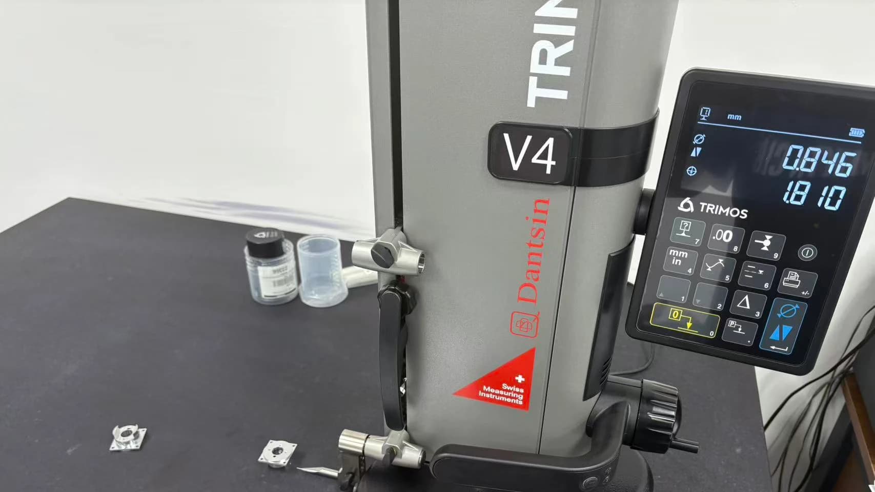
Digital height gauge on a measuring benchRepresentative visual

Process comparison

Choose the control that matches the requirement

This table is a drawing-preparation aid, not a capability promise. The correct control depends on design intent and the applicable drafting standard.

Requirement typeUse it to communicateCheck before release
General toleranceDefault limits for dimensions that are not called out individually.The governing standard, tolerance block, units, and decimal-place rules are explicit.
Feature toleranceThe accepted size range of a specific diameter, width, depth, or angle.The tolerance is tied to function and not duplicated by a conflicting note.
FitThe intended clearance, transition, or interference between mating features.The mating feature, material state, and assembly condition are known.
Geometric controlForm, orientation, location, or runout relative to a datum system.The datum references are stable, accessible, and functionally relevant.
Post-finish dimensionThe accepted size or geometry after coating, plating, or another treatment.The drawing states whether acceptance applies before or after finishing.

Separate general and critical requirements

A drawing needs a clear baseline for ordinary dimensions and explicit controls for critical features. Avoid applying the tightest tolerance to every feature by default.

  • State units and the governing general-tolerance standard or title-block rule.
  • Call out critical sizes and geometric relationships individually.
  • Use reference dimensions only for information, not acceptance.
  • Check for duplicated or conflicting controls.
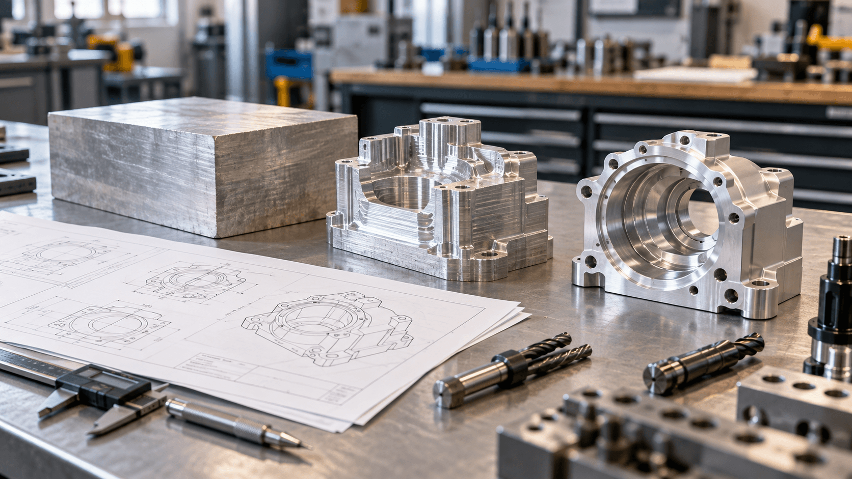
Identify critical dimensions first

Connect tolerance to a datum and function

Location and orientation requirements only become meaningful when the drawing establishes how the part is constrained. Build the datum system from functional interfaces where possible.

  • Identify the surfaces or axis that locate the part in assembly.
  • Reference positional and orientation controls to the intended datums.
  • Show the mating condition when it explains the requirement.
  • Avoid datum schemes that are unstable or difficult to access.
Improve the datum and feature layout
Digital height gauge on a measuring bench

Technical guides / Manufacturing context

Clear drawings keep technical decisions connected.

Representative media supports the engineering discussion and does not document a specific customer order.

Representative visual
03 / Project considerations

Account for material, geometry, and finishing

Achievable variation depends on nominal size, material behavior, wall thickness, feature depth, process sequence, and surface treatment. A value that is reasonable on one feature may not transfer to another.

  • Flag thin walls, long slender sections, deep bores, and interrupted features.
  • State the material grade and condition.
  • Clarify whether dimensions apply before or after surface treatment.
  • Review interacting requirements as a system rather than one dimension at a time.
Prepare material information
04 / Project considerations

Align the inspection method before ordering

A requirement should be measurable with an agreed method and datum setup. If a report, sampling plan, or approval step is needed, include it in the RFQ.

  • Identify the characteristics that determine acceptance.
  • State requested records and any sample or first-part approval need.
  • Discuss access and measurement method for difficult features.
  • Keep results tied to part number and drawing revision.
Review inspection planning

Before you request a quote

CNC Machining Tolerances: What to Specify FAQ

Use these answers to prepare the requirements for your part. Project details are confirmed during drawing review.

What tolerance can VELMEC hold?

Tolerance capability depends on the feature, nominal size, material, geometry, process sequence, finish, and inspection method. Send the drawing so selected critical features can be reviewed instead of applying a single number to every part.

Should coating thickness be included in a dimension?

The drawing should state whether a dimension is accepted before or after finishing and identify masking or buildup concerns. The finish specification and critical interface need to be reviewed together.

Can a general tolerance block replace feature callouts?

It can define a baseline for non-critical dimensions, but it should not replace explicit requirements for fits, critical sizes, geometric relationships, threads, or surfaces that control function.

Do I need an inspection report for every dimension?

Not necessarily. Identify the characteristics that determine acceptance and request the needed record scope during quotation. The inspection plan should reflect project risk and the agreed requirements.

Ready for engineering review

Have a part to make?

Send your drawings and let our engineering team review your project.

We will provide your quotation within 24 hours after we receive complete drawings and project requirements.

Make the requirements clear

Include quantity, material, finish, critical dimensions, and any inspection requirements.

STEP / STP / IGES / IGS / STL / DWG / DXF / PDF / ZIP / XLSX / XLS / CSV